- - - - - - - - - - - - - - - - - - - - - - - - - - - - - - - - - - - - - - - - - - - - - - - - - - - - - - - - - - - - - - - -
Why crossovers?
Speakers produce an astonishing range of waves! The highest frequency humans can hear requires a speaker’s driver to move back and forth 20,000 time a second in order to make those 2/3” long sonic waves. The deepest audible bass makes the driver move about 60 times a second and sends 50’ sonic wavelengths out at your room. That may sound like hard work, but speaker drivers do it every moment they’re playing music. The physics that govern what it takes to produce these waves demands different kinds of machines for the fast, short waves than for the long, slow ones. This is why speaker boxes contain drivers that are treble specialists (tweeters), bass specialists (woofers), and sometimes midrange and low bass specialists. So the first job of a crossover is to split these frequencies up and send them along to the proper drivers.

But crossovers do much more. Speaker drivers need help. Lots of help. They play louder (are more “sensitive”) at some frequencies than others and can benefit from being “equalized”. Tweeters are usually more sensitive than woofers and need to be brought into balance. The very cabinet that a driver is put into has a large effect on which frequencies play louder and therefore need to be accounted for. So, the second job of the crossover is to manipulate the signal it sends to each driver so that it:
- Is just what’s needed for each driver to sound its best.
- Adjacent drivers interface well.
- Different driver outputs are matched so that they all play at the same loudness.
And, believe it or not, there’s more. Crossovers affect the timing of when sound waves originate from a driver which, in turn, determines if the waves from other drivers meet in a coordinated fashion or not. Further, they play a large role in defining the only speaker property your receiver cares about: its impedance.
So that’s a brief description of what crossovers do. From here on, the discussion will get a little more technical so, if you’re not already versed in some audio vocabulary and concepts, we recommend that you first read “Physics of Sound” and “How Speakers Work” before proceeding. If you’re fairly well learned in this subject, put on your trusty thinking cap and proceed.
- - - - - - - - - - - - - - - - - - - - - - - - - - - - - - - - - - - - - - - - - - - - - - - - - - - - - - - - - - - - - - - -
How do crossovers work?
Crossovers create the shaped bands of frequencies that are tailored for each driver through the use of only three kinds of filters: capacitors, coils (called inductors) and resistors. Let’s look at what these filters do “theoretically”, before considering some real-world complications.
Resistors: Say an amplifier is delivering 10 watts of power to an 8 ohm tweeter. Then you place an 8 ohm resistor in line with it (in series), how much power will the tweeter then “see”? The answer is 2½ watts. The new 8 ohm + 8 ohm load tells the amplifier to deliver only half the power as before (5 watts) and half of that power is “used” by the resistor; half by the tweeter. This would attenuate the entire tweeter’s range by 6 dB if, in fact, the tweeter was 8 ohms at all frequencies.

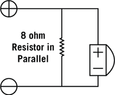
Now, if you place the same resistor across the tweeter’s terminals (in parallel), what would you expect? You might be surprised to learn that nothing will change at the tweeter. The parallel resistor reduces the amplifier’s load to 4 ohms, causing it to deliver twice the power, but all that extra output gets shunted through the new resistor, leaving the tweeter unfazed.
Capacitors and Inductors: A capacitor placed in series with a speaker, as shown in the schematic below, will block the low frequencies and pass the highs on through. Notice that the “roll-off” slope is fairly gradual and smooth – this is the theoretical slope that occurs when the tweeter has a flat frequency and impedance response (they remain constant with frequency). The steepness of the slope eventually reaches the point where it attenuates 6dB for every octave further away from the tweeter’s operating range. This is often called a 6dB/octave or 1st order rolloff slope.

Maybe the crossover designer wants a steeper slope so that the tweeter won’t receive so much energy below where it operates well. They may try something like this, which results in a 12db/oct or 2nd order rolloff slope.

Steeper slopes – 3rd order (18dB/oct) & 4th order (24dB/oct) are sometimes used – can be obtained with more parts. Changing the part values will result in differently shaped slopes – maybe you’ve heard of Linkwitz-Riley, Bessel, Butterworth (not the syrup) or other kinds.
Next, let’s see what happens when we throw a woofer into the design:

Notice how the total speaker output in the crossover zone depends on the sum of the woofer’s and tweeter’s outputs?
- - - - - - - - - - - - - - - - - - - - - - - - - - - - - - - - - - - - - - - - - - - - - - - - - - - - - - - - - - - - - - - -
Real world complications
So you’re thinking, “That’s pretty easy – Just figure out what frequency and slope type I want, then pick the part values off of a chart.” If that were true, crossovers could be designed in a few hours instead of a few weeks or months! Unfortunately, once real drivers and enclosures come into play, the above crossover might produce a graph something like the one below. Real parts introduce eight complications worth looking at:


Drivers don’t have perfectly flat frequency responses. If these deviations occur near the crossover frequency, adjusting the parts values in the crossover can sometimes adequately address them. Other times, a notch filter can flatten-out a peak.
Tweeters are almost always more efficient than woofers and need to be brought down to a suitable level. This is done with the use of a resistor – an all-pass filter – that attenuates all frequencies evenly if it weren’t for some of the other five problems.
Waves can do some funny things. For example, waves shorter than the surface that makes them tend to beam their energy forward, kind of like light from a flashlight, while waves significantly longer than the front surface of a speaker, wrap around the enclosure and disperse pretty much evenly in all directions. The result is a lower energy density in front of the speaker for the evenly dispersing bass than for the forward directed higher frequencies (shorter wave lengths). This 6dB bass loss, sometimes called a “diffraction step,” means that the rest of the speaker’s output will need to be brought down to the now lowered bass level (unless the speaker near the wall behind it where waves are prevented from wrapping around). Often speaker designers will accomplish most of this by increasing the value of the first coil in series with the woofer, which is why it can be 2 to 4 times larger in value than what a chart prescribes.

Here’s another interesting thing waves do. When two waves of the same frequency meet, they band together (if they’re “in phase” with each other), totally cancel each other out (180° out of phase) or only partially help one another out. With speakers, this happens in the crossover zone where two drivers share the same frequencies. In the graph to the left, the drivers are 180° out of phase with each other even though they are both wired “positive to positive” – because the rolloff slopes introduce phase shifts of their own! Simply wiring the tweeter “backward” (with amp positive to tweeter negative) can correct this problem. But, if the phase differences tuned out to be, say, 90°, then there would always be some cancellation and the driver outputs would need to be increased in the crossover zone to compensate. The rule, if not for still other real world compromises, is that even order slopes (2nd, 4th) cross over 6dB below the overall speaker level (with 2nd order slopes requiring one driver with reversed phase); odd order slopes cross over down 3dB.
So you can see that controlling the rolloff slopes, both output and phase, is important for getting the drivers to sum properly. But the slope that matters isn’t what comes out of the crossover – it’s what comes out of the drivers. This means that driver’s natural roll-offs characteristics, the crossover’s rolloff (and more) all work together to produce the properties, both phase and amplitude) that determine how well the sound from the two drivers will integrate through the crossover zone.

When two drivers share the same frequencies, the amount that their waves add to each other also depends on where the listener is. The illustration above shows a speaker with a tweeter positioned above a woofer, a green listener, who is standing and a blue listener who is sitting down.
Let’s look at what happens at the crossover frequency – 3000 Hz in this case. The woofer and tweeter waves arrive at the standing (red) listener at the same time and add together. But for the sitting (blue) listener, the waves from the more distant tweeter arrive later than the woofer’s. He happens to be 2” closer to the woofer than the tweeter – ½ of the 4” wavelength at the crossover frequency. So the pressure wave from the tweeter arrives at the same time as the rarefaction wave from the woofer (180° out of phase) with the two waves canceling each other out, resulting in the same graph as in point 4) above. By the way, this is why drivers are usually above one another, so that this problem will manifest itself vertically – hopefully above and below the listening area.
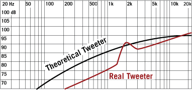
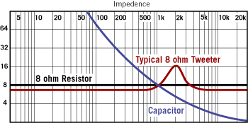
While it’s easy to think of crossovers as filters that divvy-up the frequencies and send them on their way, they don’t really work like that. The amount that a crossover attenuates a driver depends on how much impedance it presents compared to the driver. Unfortunately, drivers usually have impedances that fluctuate greatly over their operating range. The graph below shows the impedances of a high-pass filter (capacitor) in blue, an ideal tweeter (resistive) in black and a real tweeter in red. The graph to the right shows the energy the idealized tweeter receives (again black) compared to what our real tweeter receives (red).
The last real-world complication worth listing here is that crossover parts have many electrical properties in addition to what they’re designed to have. This makes for effects that are different than what a textbook would predict.
- - - - - - - - - - - - - - - - - - - - - - - - - - - - - - - - - - - - - - - - - - - - - - - - - - - - - - - - - - - - - - - -
In Conclusion
A while ago you may have been thinking that crossover design sounded pretty easy – but now you’re convinced that it must be close to impossible. The truth is that it’s really not that bad if you know the secret that many speaker designers keep to themselves – that it’s speaker performance that matters, not theory. Designers don’t need to calculate adjacent slopes, how the sound from two sources will add together and so on. They can just fiddle with everything until they deliver the desired sound — though it’s very true that knowing the theory makes you a much better fiddler. And now there are good computer modeling programs that can get a designer pretty close. But the process really comes down to fiddling with parts, measuring frequency and impedance character, listening and repeating over and over again until the speaker performance gets the big thumbs-up. Which is why good measuring equipment, a panel of golden ears and a good listening room are as indispensable as a phD in crossover theory.

Complete Your Sound System Solution

Sign up for our newsletter below, and join our social media groups to stay up to date with the latest news and information from Aperion Audio!
 |
 |





 https://www.aperionaudio.com
1 comment
Hi, That is probably one of the best ‘non-tech’ explanations around crossover design, and the actually real world complications of getting to one that sounds ‘good’ or hopefully ‘excellent. To me, assuming the ’loudness’ is achieved, and decent bass drive, then it is all about the PHASE. If the drivers are not working together in phase – in harmony, then speech – vocals will always be hard to decipher, and stringed instruments will sound good sometimes, and harsh the next track. Not to mention percussion and cymbals! Always audition speakers with real instruments, and if they can recreate close to a live performance of say the Chieftains – with all the Celtic fiddles, drums, bag pipes, then you have something that Sheryl Crow or Squirrel Nut Zippers will sound good through too! And Jazz, piano, Rock Pop, etc.